Conclusions

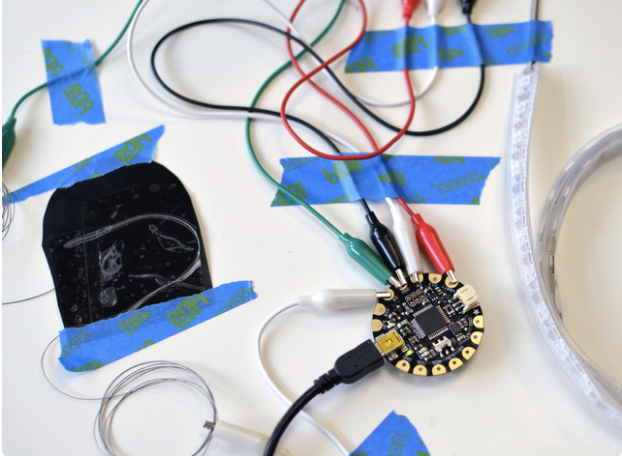
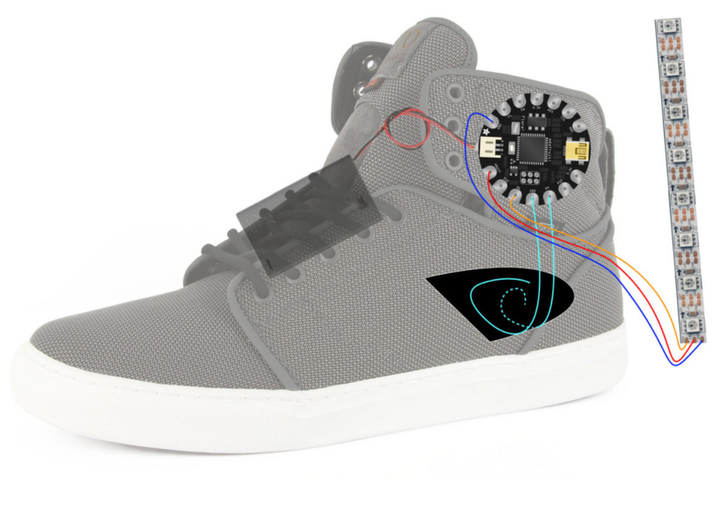
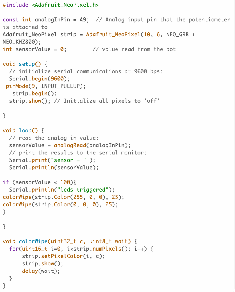
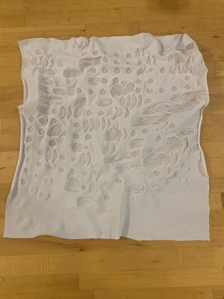
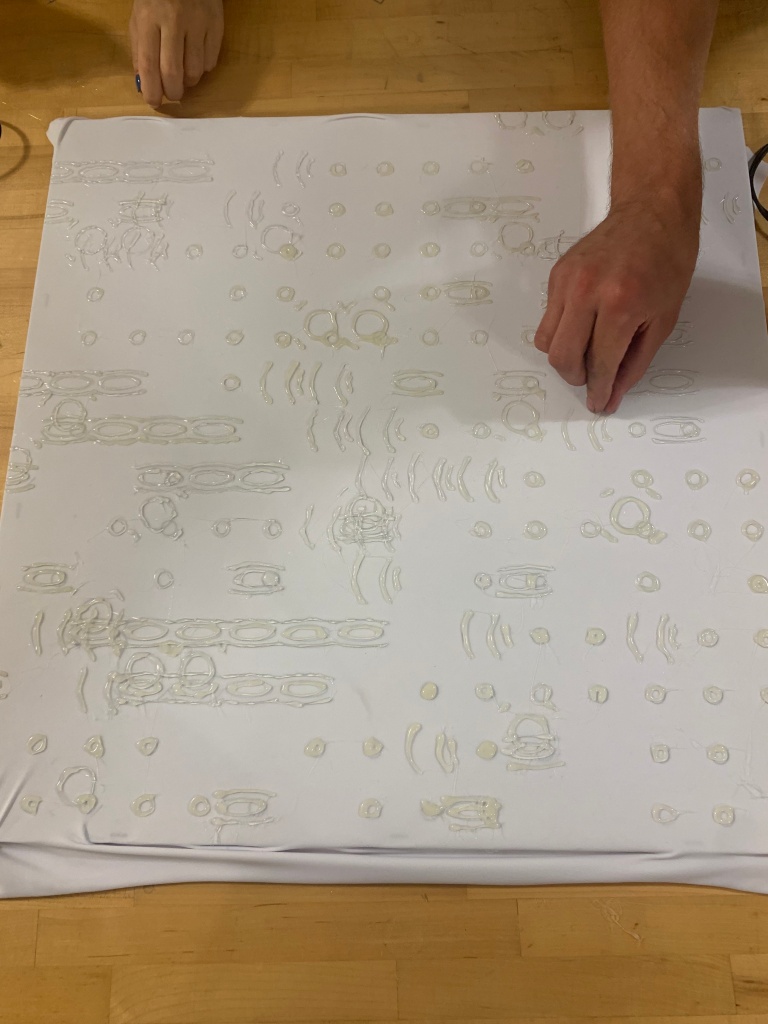
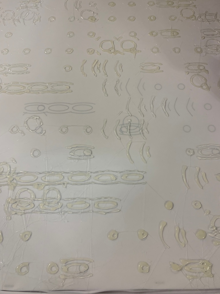
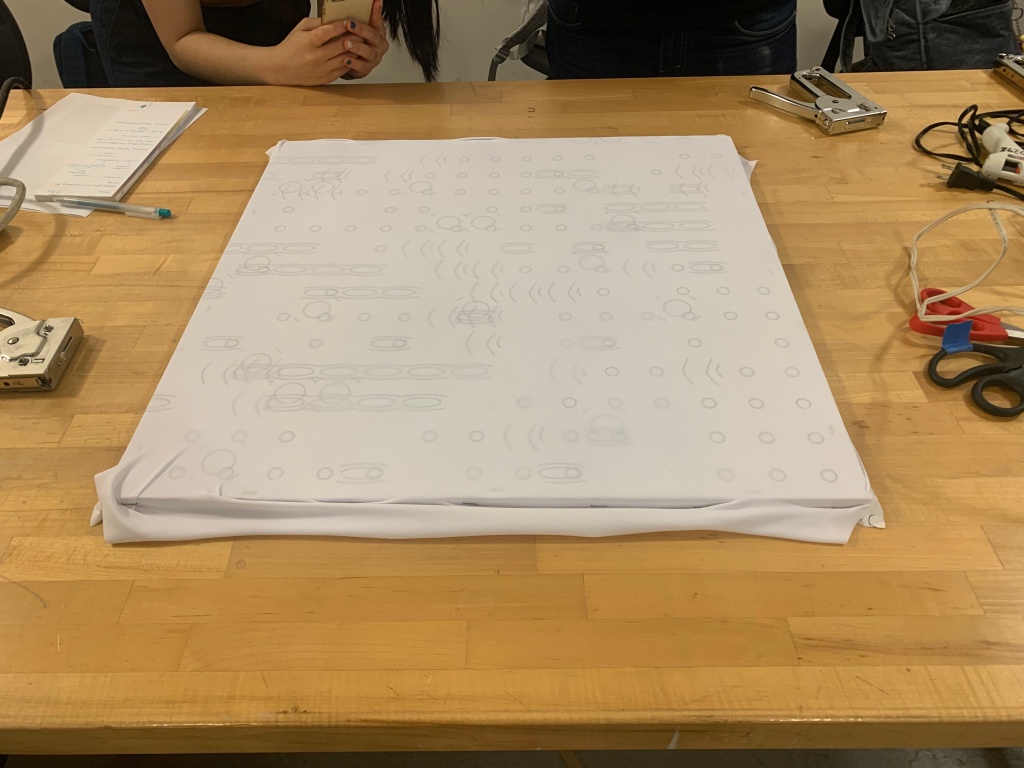
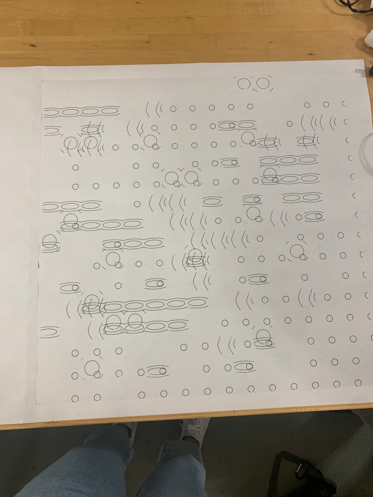
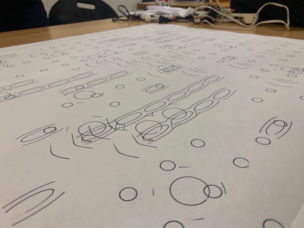
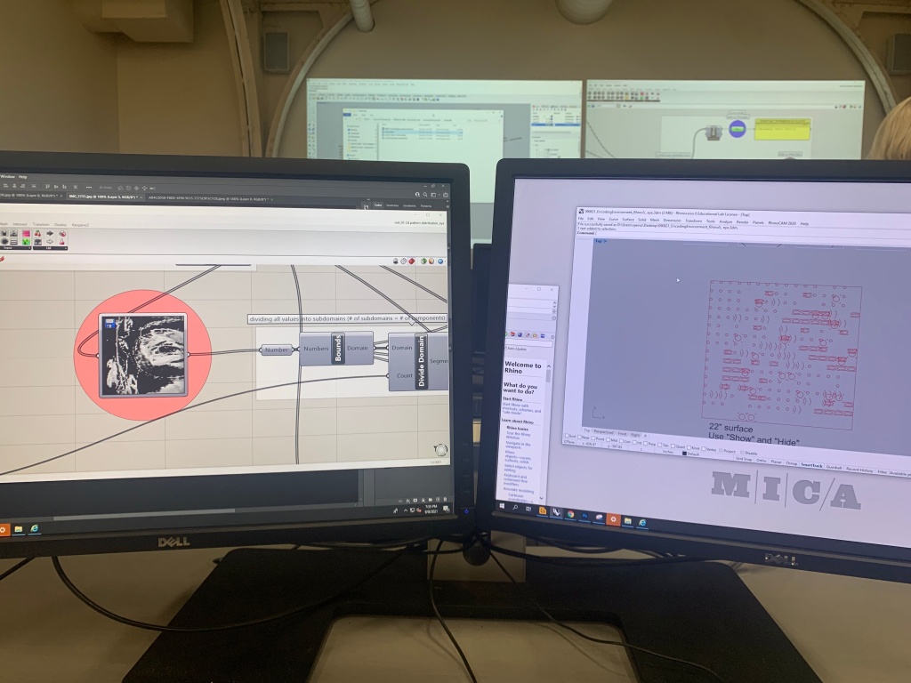
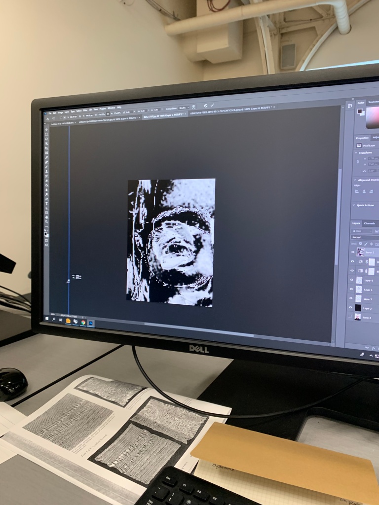
The three images above detail a rough overview of the process of this project.

My research question: Can digital topographic visualizations be utilized to generate physical depictions of landscapes?

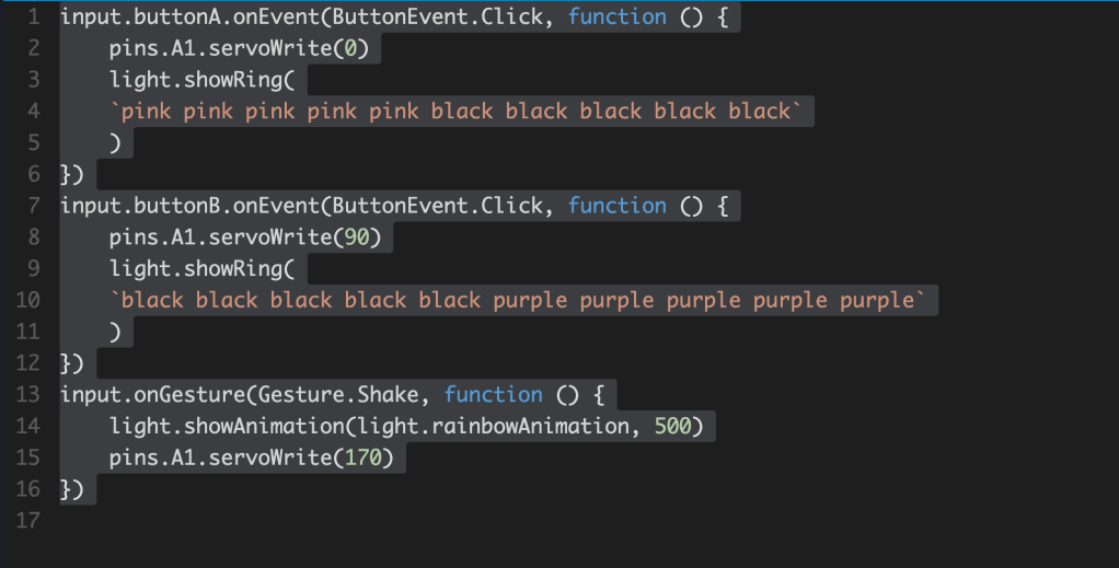
I was able to generate physical depictions of a landscape by using various digital programs and plug-ins such as Cadmapper, Rhino, Grasshopper, Xylinus (created by Ryan Hoover), G-code, and PronterFace.

I first took a topographical map of the Inner Harbor from Cadmapper, then imported the file into Rhino. With this information, I took the surface of the topographical input, and with the help of Ryan Hoover, utilized Grasshopper to register the various coordinate points according to the landscape of the Inner Harbor. Using Ryan’s plugin for Grasshopper called Xylinus, where coordinate points can be exported into g- code to be then be imported into Pronterface. In Pronterface, the software used to make the 3D printer function was coded to push individual pins in the z-axis to reflect the landscape of the Inner Harbor.

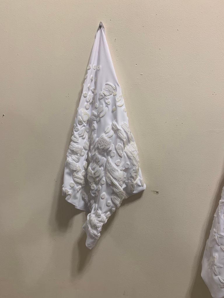
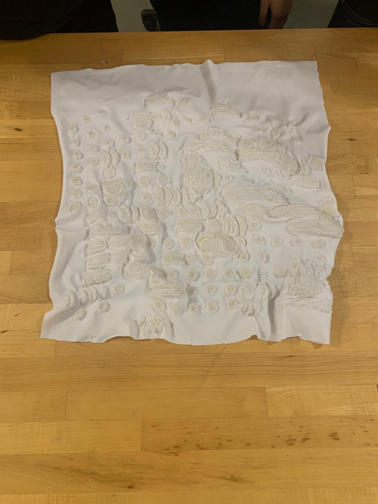
My finding was that landscapes can be recreated in a physical manner by utilizing the mechanics of a 3D printer and introducing the functions of Pin Art to move individual pins to different lengths according to the elevation of a landscape.

Troubleshooting

Since the printer, I am altering originally served a different purpose, it has measurements pertaining to its original functions. This makes the z -axis wire, that is connected to the motor, too short for the new function of the printer.

I had to extend the length of the wire to reach the new set distance. I did this by cutting the original wire and stripping the ends and then sautering a new piece of wire to each broken end of the original wire.

Prototypes Phrase 2

The image below is the mounted piece I designed to hold the motor and metal rod. This two-piece mechanism will allow the rod to move on the z-axis and move the pins in a vertical motion to recreate a landscape.

The drawing above was an early mock-up of a stand where the printer would live. The design displays the series of suspended pins the printer would move to generate the landscape.

Research: Development Stage 3

This week I prioritized both the construction of the printer itself and a functioning G-Code, to be able to test the printer as soon as possible.

Below is a printed test for the pin holder. I experimented with both a 3d printed object and a laser plexi cut option to see which functioned better.

It was recommended, I build a type of washer to help suspend the pins in place for when they are pushed upward. The washers deemed promising for some holes and others not so much. I will need to trouble shoot how to make every hole have a washer that stays in place.

Research: Development Stage 2

My process thus far, has consisted of constructing both the machinery and technology to allow my project to function as planned. In the previous week I had prioritized learning more about the mechanics of a 3D printer and discovering how it would function in terms of my project. This past week I focused on developing the grasshopper script that will translate the input information of coordinate points into a G-code script for the printer to read. Ryan helped me tremendously with better understanding the workflow of Grasshopper and executing the proper grasshopper script.

The script above provided the coordinate points. These coordinates were translated from the topographical input, it was crucial to ensure the z-axis would illustrate a function of travel upward. Functions that were crucial to the execution of the script include commands such as ray, point deconstruction and remapping. Below is my hand written illustration of the process of the grasshopper script.

Taking the time to retrace the process of construction of this Grasshopper script allowed me to better understand the mechanics I would need to construct for my 3D Printer. I was able to build the grasshopper script found below to build another important part of my printer. The pins that will rise and move on the z- axis need a base, this base needs to fit and properly hold these pins.

The script functioned properly but was unassigned a surface after I baked it.

During this class I began to look more closely at the construction of other 3D printers and gained inspiration and knowledge from observing them closely.

The printer I have envisioned to construct will require no nozzle but instead a push system. The printer will have no filament, instead it will push pins upward to a certain height to mimic topographical outputs.

Research: Development Stage 1

In efforts to better understand the mechanics and functions of my envisioned design, I chose to make a rough model. I was focused on exploring how the pins could hold their position and not be subject to falling out. I was also interested in better comprehending the scale at which my input information (photographic imagery) was scaled at versus what scale I would choose to represent for my topography.

I realized this model would need much more redesigning than I anticipated. The scale of this model allowed me to see my topographic measurements would need to be smaller than anticipated.

Gathered Information & Timeline

Gather Information:

This past week I was able to use an 3D printer to build my model for the redesign of a park. Being able to trouble shooting on a regular 3d printer allowed me to better understand it’s functions and capabilities. Below near the bottom of the image you can find my 3D printer model.

Timeline

November 3 – Before Class:

-Learned more about software (Arduino, Marlin- config. h , Proferface).

-Run preliminary test on pin sizes as well as design a rough idea of the inclusion of the pin art.

-Have selected and edited images to be 3D printed (pick varying geographical landscapes).

-Process on including the Encoding the Environment script and seeing how I can alter it.

During:

Test run the 3D Printer to see if functions as I envision it could.

November 10 – Finalize the mechanics of the 3D Printer. Have a prototype for the pin art attachment and selected pin size.

November 17 – Finalize the Coding aspect of the project.

December 1 – Look into the redesign of building a new printer.

December 8 – Project Completed & Photographed

December 15 – Show Opens

Research: New Approach

After giving my presentation for the class, and speaking more in depth about my design process and spacial contextualization of spaces. I dwelled further on my interest of perceiving information in both the 2D and 3D realms.

I began to think if there was a way I could take a 2D map/topographical input and make a 3D output. This thought reminded me of a children’s toy I have seen before. What is traditionally known as a Pin Art Toy, where pins lay flat and with the placement of a hand could this pins take a new form.

In order to accomplish this product of recreating topographical outcomes based off of 2D inputs I originally was going to generate a sensor for each pin to move independently. This would require a large amount of sensors and careful sauntering each pin to a sensor. After deliberating with Ryan, Alan, Vic, Annet, and Margaret, this process may not be the most efficient and proactive.

My approach my require the utilization of a upside 3d printer, which could generate the same outcome of moving pins and holding their position. The biggest benefit to this solution is not have a series of sensors or materials instead of just the 3D printer which would require a G-Code.

My research process will now consist of discovering the necessary materials I will need and task I will need to complete in order to make this project function.

Speed Dating

When asked to pitch our ideas to each member of the class my initial research question I proposed was “Can we measure geographical visualization by means of map making in manual and digital methods?” 

I am interested in investigating the methodologies of the Marshall people and see if I could apply the same logic to new technologies we learned in class. 

I envisioned the process to take shape by having a 2D image of a topographical reference, have the “Encoding the Environment” grasshopper script record the varying color shifts based on elevation or landmark. Then this visualization could then be placed into the AdaCAD software to translate the visual into a weaving format. The saving would then consist of different weaving techniques to demonstrate different landmarks or elevations. The output would be a constructed weave in which someone may be able to read as a map. 

During the speed dating process, we were asked to write skills we had personally and skills we were looking for from our classmates.  I noted that i have good rhino skills, rending skills, fiber skills, brainstorming skills and designing skills. I mentioned needed skills on TC2 Training, Floor Standing loom knowledge, coding and sensors skills. 

I am interested in generating a multitude of maps and seeing how and if audience members are able to read these maps themselves.

Generating A Narrative

The basis of my presentation was centered around my cultural upbringing of being raised in a Colombian family living in the United States. I often found myself traveling to Colombia and attribute my close ties with my South American roots because of being able to visit often as I grew up. Being bilingual by a very young allowed me to depend on language based narratives and develop a strong understanding between my spacial experiences and being able to express these spaces and events in verbal language. I tied my visualization of spaces and landscapes to language to helps me make more sense of what I am experiencing in any given moment.

My personal experiences and hearing others experiences are what inspire my art pieces and what allow to generate creative outputs. From my inspiration I try to recreate or generate new spatial experiences.

In my work, seen above, I am constantly in dialogue with 2D and 3D languages to create spatial encounters. For this specific piece I created a 2D net to form a 3D inflatable home, where people can enter and explore the pieces construction. 

I am interested in the Marshall Island maps, there is a sense of 2D and 3D construction and communication, this idea reminds me of the a similar concept to GIS softwares. GIS translates to Geographical Information Systems, this layered sense of information is one I would like to introduce into my research project.

Formulating a Research Question

In my process of further discovering my research topic, I began to think back to the Encoding Environments workshop with Marantha. I began to think about how I interpret spaces, more specifically sites. As an architectural designer, I am constantly reassessing the site of any design proposal, in order to understand what it is the site itself is requiring of a design. I usually contextualize a site in identifying the items of importance such as topography, vegetation, area quality, etc. All of these findings of a site analysis can be found and displayed on a digital format. Google earth itself can provide and aerial view of a site and even make a 3d view of the site. Yet, I find myself engaging in other forms of methodologies to better understand the site, that being model making with fabric, wood, brick, etc. I search for ways to contextualize a site better and am interested in being able to create a way in doing so, by incorporating skills we learned in the course.

I had mentioned before my thought/design process of intersecting language with symbols to then generate forms for my designs. Knowing this I began to look at ways of translating information in means of handmade material, during this process I researched the Marshallese Stick Charts. These charts were originally constructed by ancient mariners from the Marshall Islands, in effort to understand the vast pacific ocean. The material they used to construct these charts consisted of coconut fibers and shells. The placement of the fibers and shells indicate the location of islands, waves and currents.

These navigational methods are recording and passing along information for others to use and build upon. I am interested in seeing if using the methodologies in our encoding environment workshop could be used to take imagery of landscapes in plan by identifying key elements to map such as water, vegetation, etc. With the results of this patterned information could these symbols be transformed into a weave structure to generate the same result of what these Marshallese Stick Charts did, record and disperse information of a geographical location.

Image of a Marshallese Stick Chart

Image of Marshallese Stick Chart

Arduino Development

For this class we will be introduced to Arduino. The purpose of this workshop was to utilize sensors to generate different outputs. I had never before tried using sensors before and found myself very far removed from creating some time of reaction from using sensors. After the workshop I didn’t feel as unfamiliar to the logic, more so the the process of coding.

This workshop began by sauntering resistors to small LED bulbs. We did this so there would be a clear form of conductivity.

The Arduino was then connected to the computer where python could be opened and coding functions could be edited and altered.

Depending on the coding embedded into the Arduino device could wires be specifically place to set locations on the Arduino and conduct electricity with the touch of a button or in a timely manner, depending on the coding.

Code Searching

FireWalker Led Sneakers

Since I can remember I have always heard of sneakers that light up, especially for shoes for a young audience. I had never really understood how the process of making a shoe light functioned, and is the reason I chose to investigate further this technology.

The installation of this Arduino was the cause of the lighting up of various colors. The wire connections from the Arduino to the LED lights run around the perimeter of the show.

https://learn.adafruit.com/firewalker-led-sneakers/test-circuit

Makey Paper Craft

This Project – Makey Paper Craft deemed to be simple in appearance but not in process. From what I was able to understand the Arduino is an already existing piece of machinery in which can be manipulated to recreate this project.

The Adruino was able to allow the piece of machinery to move when pressure from physical touch was applied to the sensor.

https://learn.adafruit.com/makey-paper-craft

Weaving with a TC2 Machine

This class we further explored the possibilities of constructing weaves by utilizing a TC2 machine. This method of making is meant to be a culminating moment as it combines analogue with digital.

.Lauren demonstrated how to use the TC2 machine. Each of our patterns were placed side my side on the same loom, with selvage space in between to maintain the design and strength of the weave. I did not anticipate the TC2 to be as manually driven, I presumed the tactile-ness of weaving would be lost. Instead this type of machinery engaged the whole body just as the traditional free standing loom does. The TC2 provide to be a machine easy to understand in how to generate the loop. When a single color was used the technique was rather repetitive and easily intuitive. Once the usage of two or more threads was introduced into the weave, keeping track of which thread to draw across required focused attention.

The introduction of conductive thread is accredited to Lauren and her research taking place at the Unstable Lab in Boulder, Colorado. She measure the energy efficiency depending on threads and manipulation of the constructed weaves.

In efforts to create a dialogue between human-made and digitally made, I decided to construct a small knitting patch and embed conductive thread through it. Images of this sample can be found below.

We were provided tester to test the resistance of the conductive threads found in our various weaves. I tested both my knitted pattern and my TC2 weave.

By the end of the workshop, I can see the resemblance in the weave and my design from AdaCAD. Something I would do differently would be to pay even more attention to generating pattens with more warp moments to construct a stronger weave. Structurally my weave may need to be reenforced but the conductivity of my weave proved to surprise me.

Preliminary Research Topics

My design process has always consisted of the associating and assigning language to graphic reference and from there I generate my designs. Essentially I create my own language system for each of my projects. This idea of generating a language for the construction of a design is a thought I have been dwelling on.

When we began to explore the processes of weaving and the connection between write commands to generated patterns intrigued me. I became to think about generating my own language to construct a 3D design. Similar to a QR code, when scaning it you are taken to another page. Would the “reading” of my weave be able to generate a 3D design? Could buildings be constructed by the creation of weave formats? Is that not what 3D printing is?

AdaCAD Experimentation

When I was first introduced to the AdaCAD software, I began exploring the various types of functions the program provided. Above are simple geometric patterns I made in my initial times using the software. These patterns were exploratory shapes rather than feasible patterns for weaving.

Once I became more familiar with AdaCAD software created by Laura Devendorf, I began adopting my knowledge of warp and weft of a weave to my design making. This software allowed me to generate a series of patterns by the utilization of various weaving techniques. As my work flow became more complex I started to run into areas of space to large for my liking. I wanted the weave to have a sense of structure that was noticeable at first glance.

I appreciated the visualization of how different patterns were generated depending on the input of existing patterns. While constructing these patterns I became interested understanding how the loom maintained its pattern, especially if the ends stopped instantaneously. The Selvage command actually helps the weave not loss its shape by almost sealing the ends with a small and tighter weave.

Above is the image of my selected pattern, that I will later on go to make on the TC2 under Lauren’s guidance.

What is Cybernetics? By Norbert Wiener

The author’s concept of feedback makes the interpretation of machinery and technology a more inviting concept. Feedback is generally associated with a proactive intention for better something. This approach seems contradicting to his original published comment on “the modern industrial revolution is bound to devalue the human brain.” This written statement of his seemed to enable technology at the expense of people’s lives rather than a service.

Why is it that people may  assume the usage of technology is the replacement of human capacities instead of the advancement and amplification of human achievement. After this reading, I began to gather a theory that the sense of authority/ control technology now has embedded into it, allowing people to think there is no need to assert their control of a process because the machine takes care of it all. Are we becoming more hands free? The reading goes into depth of how the control(capabilities) a machine has occurs through the process of “sending messages which effectively change the behavior of the recipient.” Technology becomes a response and/or translation system for a multitude of tasks. 

These translated systems machines create to an extent have created a widening gap of loss of information between the user and the outcome. And an example of this could be when a student uses a calculator for a math problem. Before calculators were accessible mathematical problems were solved entirely by hand. So give a student a graphing calculator to solve a problem, they’ll ideally solve it correctly. Now give them a similar problem and remove the graphing calculator, will they be able to solve the problem? Will it take them longer to solve the problem? Will they reference the process of the calculator to solve the problem or will they have relied so much on the technology that they have a gap in their knowledge of solving the problem?

Hand & Digital Weaving

I was introduced to weaving in a fibers course before attending MICA. In this same course I learned the meaning of warp and weft. I was interested in how to generate a series of patterns on a loom. Having learned the basics of weaving I quickly transitioned into construction tapestries. I began wanting to better understand the construction of a weave by trying to dissect it. (reference photos attached). 

I have always wanted to try using a free standing loom as I have seen its type of capabilities in the past. Now having experienced using one, I believe that having attempted to weave by hand first allowed me to understand the construction of a weave.  

I had never before used or understood how to use the free standing loom. I was interested in learning the machinery behind the construction of a weave. Once I was able to maneuver the foot pedals I better understood how the pattern was made on the free standing loom. As I was weaving I began to think of the outcome of the weave while being in the process of making the weave. This sense of understanding and visualizing the outcome made the transition to digital weaving easier. 

At times softwares like grasshopper skip the visualization of a process. In grasshopper words mean actions versus in a hand made process, physical action is required to generate a result. Both processes result in visual feedback; the difference is the clarity between a digital process versus a handmade one. 

Now having worked in both methods, I find both processes have the flexibility to generate complex weaves. 

On Weaving By Annie Albers

In the reading, Albers details how weaves are constructions of the three main types of weaving patterns: the plain weave, the twill and the satin weave. These patterns function almost as an interpretive  language to identify the structure of a weave. Once learning how these weave patterns look, it’s much easier to regenerate a weave from another. You can begin to understand the construction once you acknowledge the pattern. You generate findings for each type of weave pattern, this encourages you to then be able to more easily decide your constructed pattern. 

I was intrigued to learn that the definition of a weave is the interlacing of two distinct groups of threads at right angles. Presumably I had never considered this as the definition of a weave as it seems a very straightforward definition. But now taking this definition and the knowledge about the three patterns, I more strongly understand how weaves correlate to graphics systems. The weave, in theory, becomes a grid structure with a series of patterns and transitions. The structure and integrity of the weave are associated with the patterns used, more consistency in preserving the original weave pattern the stronger the weave. 

Before this course I had not imagined constructing a weave in a digital format or relating it so closely to technology. Yet, once I was reintroduced to weaving as a series of systems to create and regenerate, and understanding its foundational elements of construction, using a digital format makes me intrigued to try complex patterns and test the limits of weaving. I felt this thought to connect well with a line shared in the text, it read, “Acceptance of limitations as a framework rather than as a hindrance, is always proof of a productive mind.”Even though weaving is traditionally an art of manual labor, I do appreciate the flexibility of technology to test variations of patterns to construction.

Encoding the Environment

During Marantha Dawkins’s lecture, I was intrigued by the idea of identifying the endpoints of bounded objects versus field objects. She utilized the example of the boundary of a tent versus the boundary of smoke coming from a campfire. This idea of measuring the threshold of nature or objects was a rather innovative idea. 

The basis of the workshop was to map a natural element into a constructed algorithm to generate a new pattern, one that essentially mimicked or recorded the variable of the natural object. The pattern of each group was altered by the input of information that was being mapped as well as the selection of imagery chosen to depict the input.

My group and I decided to layer photographs of each of our faces into one to generate one image. The images were edited to be in black and white with a high contrast level. The image of our faces joined together was a close-up of our right eyes. We chose to concentrate on one specific area to get as much detail as possible. We choose to map a total of three different color contrasts for our new pattern.

The symbols chosen to depict each different color contrast became relational shapes that alluded to the form of the eye or the mechanics of an eye. 

The high contrasted image of our eyes was placed into the grasshopper script and generated a pattern of overlaying moments, which interestingly enough was a process we had previously created in Photoshop.

After the printing of our constructed pattern was complete, we placed it under a sketched fabric for tracing. We chose to layer glue at the interesting points of our pattern so the end result would be as accurate as possible. One of our chosen symbols allowed for the directional pull of the fabric to create variations of height.

The final product of our pattern resulted in a series of concave and convex elements/moments that were constructed by the selection of our symbols.

Unravel the Code

My interest in this class: Unravel the Code,  was sparked by wanting to learn more about emerging technologies and how they contribute to facilitating design processes.

I consider myself both a digital and fine artist. I have in the past worked with ceramics, plastics, fabrics, etc, to create sculptures. I best communicate my interest in spatial relationships through sculpture or visual renderings. Both of these processes I enjoy doing and am wanting to expand my knowledge in both realms. I hope for this class to blend both my fine art skills and digital skills.  

Design a site like this with WordPress.com
Get started